3D rendering geometry
While a human is able to do one complex task easily at one glance (locating people in a picture), the machine can only do very simple task but it does it very fast. This shows in the way graphics are rendered on screen, up to the geometric level. The scene below appears to the eye as composed of many complex objects. In modern 3D computer graphics, each of these object is usually divided in triangle shapes, the sum of it forming the object’s geometry. Add to that a bit of shading and post-processing, and you get the scene as you see it.
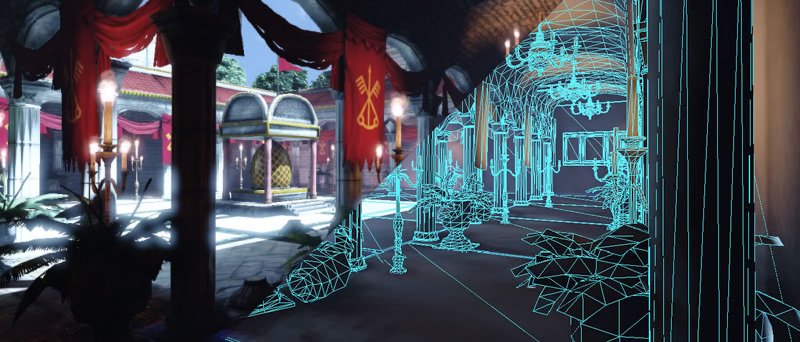
Why using triangles? Because they are the simplest possible surface. 3 points define a surface (triangle) while two would only define a line (segment). Add one more and at best you have a quadrilateral, at worse you have some weird volumetric shape that is hard to interpret. So, if you want to use a surface to define an enclosed volume, triangles are the best building blocks. No wonder it’s the lingua franca in graphic processing!
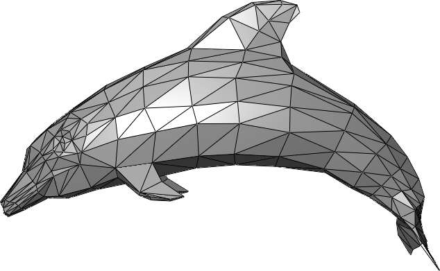
So, your geometry is based on triangles. What are your triangles based on? Well, on dots, that holds a lot of information: their position in space (necessary) and other optional informations (colors, normals…). These have a more formal name: vertex (plural: vertices). All geometry you’ll encounter is based on a set of vertices, usually read as a set of triangles. You can go simple stuff (a square -two triangles-, a cube -twelve triangles-…) and more complex and eye-appealing forms.
Pipeline Overview
How do we go from a barebone 3D mesh to a fancy textured post-processed scene displayed on your screen ? The magic happens on the graphic card, transforming vertices into final pixel colors. This process is called the graphic pipeline. This pipeline contains a series of steps through which every frame will be processed.
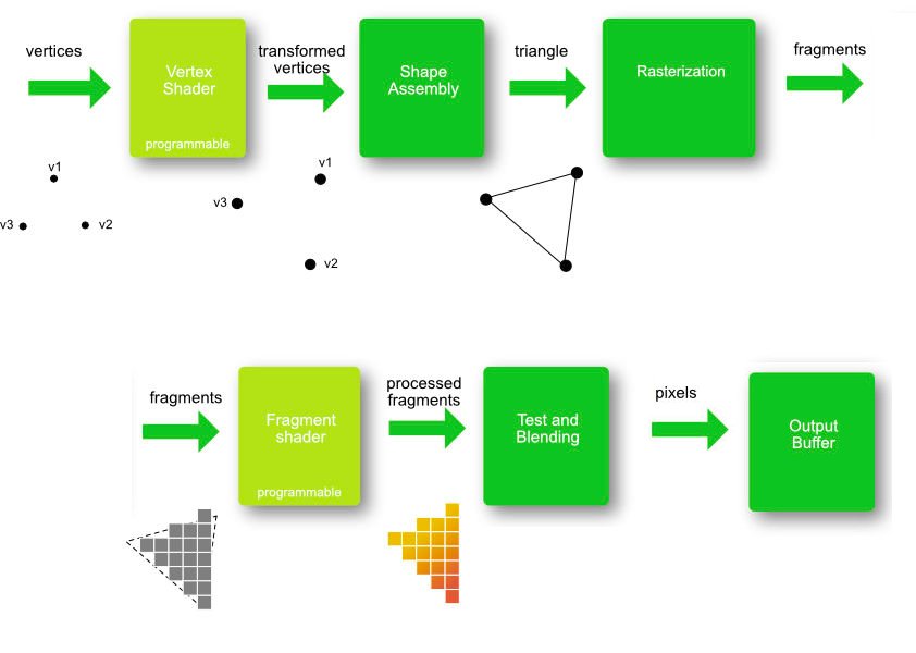
- First, the Vertex Shader will alter the vertices themselves (the positions in space) through translation, rotation, scaling and other shenanigans. This allows for instance to place your mesh at a specific position;
- Then the shape assembly will decide how to read this list of vertices. Usually (not always) they will be read as series of triangle surfaces as we wrote earlier. They could otherwise been seen as dots or line for instance. We’ll play with that in another log;
- Then it’s time for the rasterization: up until now, we had coordinates in 3D. But news flash, your screen is 2D and discrete: pixel based. The rasterization is this projection from the 3D space to your screen. It transforms shapes in set of fragments, temporary pixels that still have to pass several test to earn the right to be displayed;
- Another shader: the Fragment Shader will run for each fragment defined at the previous step, and will define the final color of the fragment, depending on the texture, fragment position or any other parameters you would feed it.
- Last, series of test are being done to discard fragments that wouldn’t be seen in the end (hidden by others for instance) in parallel of blending whenever you happen to have fragments that will mix together (for instance with transparency). The survivors of these tests and processes are finally called pixels. We finally got them !
Two steps are of particular interests. Spoiler alert, it’s the shaders. What makes them so interesting? You can program it. It’s not anymore accessing stuff and ordering your graphic card, now it’s about uploading programs directly on your GPU for them to be executed over each vertex and each fragments.
OpenGL/WebGL state machine
In order to use WebGL, we first need to initialize its context. Initializing the context means to put in a certain state the system. One of the various ways to use WebGL is to modify its state. That’s why we say that OpenGL/WebGL is a state machine. Having a hard time following? Imagine you’re having felt pens of different colors. Whatever you’ll draw will be drawn in the color of the felt pen you’re handing. If you’re changing felt pen, you’re changing your state (in the sens that you’ll be changing the color of what you’ll draw from now on). There are multiple states in WebGL, some related with colors, other with geometric operation, and so much more you’ll discover along the way. The sum of all those states forms the openGL/webGL context.
Another level of complexity
Ok, the please do all function was nice and all, but the higher level the function, the less control you have over it. Let’s dig deeper. For that, we’ll divide our main function in 4 parts that will mirror each of the processes we outlined in this log up until now. First you will have the initialization of the WebGL context, then we’ll create the shaders and create a geometry (a simple triangle in our case).
These three steps can be done once for all, in the setup function. On the other hand, the drawing needs to be repetitively done, for each new frame. In other words, each time we need a new frame, we need to call a drawing function. Let’s already define such a function (outside of setup) and call it draw. At the end of it, we use requestAnimationFrame to make sure it’ll be called anew for the next frame. Then we call it once in the setup function to launch the loop.
Luckily, you don’t have to write allll that code yet, we have sub functions that will handle that for you as you can see below. The first aim of the following logs will be to understand those functions and replace them by your own code.
// Your setting up. Called once, at the beginning
var setup=function() {

  // You set up everything
  OTSHelper_initGL("my_canvas");
  OTSHelper_createShaders();
  OTSHelper_createTriangle();

  // Launching the first drawing
  draw();

};

// Your drawing function, called repetitively for each new frame
var draw = function() {
  OTSHelper_draw();
  requestAnimationFrame(draw);
}